IV. TRAUMA TO THE MANDIBLE: LOWER FACE SERIES
1. Panorex: Best single view short of a CT for viewing the mandible.
-View of choice for viewing condyles.
2. Lateral Oblique: Excellent for viewing the mandibular body and ramus.
– film-5×7 screen film usually hand held horizontally by patient.
TO VIEW BODY OF MANDIBLE
-views premolar, molar and inferior border of the mandible; broader than PA’s
-example: Body Of Left Mandible [right to left]
x-ray tube [aimed under right side of mandible]  head tilted to left
 cassette held against side of face by patient parallel to border of mandible and extending 2 cm below it [centered on 1st molar]; 65 kVp, 10 mA
TO VIEW RAMUS OF MANDIBLE
-views ramus from the angle of the mandible to the condyle; useful for ¬ /  3rds
-example: Ramus of Left mandible [right to left]
x-ray tube [aimed under right side of mandible]  head tilted to left until a line from the right angle of the mandible to the left condyle is parallel to the deck
 protrude the mandible. This keeps the spine out of the view.
 cassette held against side of face [ramus] by patient and extending 2 cm below the inferior border of the mandible; 65 kVp, 10 mA
3. Towne’s: (anterior-posterior projection)
. -AP view w/ 30ï‚° tilt of the tube caudally
-view can be used to observe condyles, necks, rami and mandibular symphysis.
-also visualized: occipital bone, foramen magnum, dorsum sellae and petrous ridges.
-cassette held by a holding device vertically.
4. Reverse Towne’s: (Modified Towne’s)
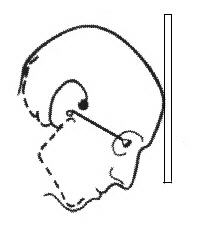
Positioning of the patient to take a Reverse Towne's radiograph
-Posterior-Anterior view, mouth open
-View can be used to observe fractures involving the condylar neck, and also when displacement of the condyle is suspected
-good visualization of the posterolateral wall of the maxillary antrum.
-cassette held by a holding device vertically.
-example: head is centered in front of film with the canthomeatal line projected 25ï‚° -30ï‚° downward; beam goes through the occipital bone; 75-80 kVp.
5. Posterior-Anterior: View used to observe the mandibular angle and body.
V. OTHER VIEWS CONSIDERED BY DENTAL
1. TMJ VIEWS
Transpharygeal Projection
– film-5×7 screen film [usually held vertically] hand held by patient
– provides an excellent “scout” view of gross changes on the condylar surfaces
– example for taking a radiograph on the left TMJ, patient’s midsagittal plane should be perpendicular to deck.
 rotate head 7 -10 away from the cassette [moves opposite condyle out of the way]
 cassette held against ear and cheekbone on left side of face by patient. The mouth can be opened or closed.
 x-ray tube directed -5 , beneath the zygomatic arch on right.
Transorbital Projection
– cassette held by a holding device vertically [cephalostat]
– frontal radiograph
– medial and lateral aspect of condyle, the neck, the eminence and sometimes the zygomatic arch.
– example for left TMJ
patient is seated with midsagittal plane perpendicular to deck and Frankfort plane parallel to the deck.
 cassette is placed behind the left TMJ  turn head 20 to the left
 x-ray tube directed +35 , from the front through the floor of the left orbit and left TMJ
Transcranial Projection
– film-5×7 screen film [usually held vertically] and is hand held by patient
– provides a view down the long axis of the condyle and the relationship of the condyle to the fossa
– example for left TMJ – patient’s midsagittal plane perpendicular to deck
 cassette held against ear and cheekbone on left side of face by patient
 x-ray tube [directed +25,1/2″ behind and 2″ above the right external auditory meatus
2. PANOREX
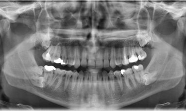
– Correctly called a pantomograph or a panoramic radiograph; Panorex the brand name of the first panoramic machine introduced to North America by the S.S. White Co. in 1959.
– The area where the images are sharp is a 3D horseshoe shaped zone called the focal trough, image layer, zone of sharpness, central image layer; therefore, correct patient positioning is critical.
– Frankfort plane parallel to the deck, the midsagittal plane, perpendicular to the deck, and the teeth in the focal trough.
– Real image – object lies between the center of rotation and the film.
– Ghost image – object lies between the x-ray source and the center of rotation.
|
ERROR |
RESULT |
| Chin too low | exaggerated smile line; loss of ¯ ant. apices; loss of condyles |
| Tongue not raised | black area over  apices |
| Patient slumped | superimposition of ghost image of spine |
| Head tilted | to left causes left to be higher on film |
| Head rotated | to left causes left to be magnified and right to be narrow |
| Lips open | black space between  the upper and lower lips |
| Too far forward | narrow ant. teeth; superimposition of spine on mand. |
| Too far back | wide ant. teeth; loss of apices |
| Chin too high | reverse smile line; hard palate superimposed on apices; condyles lost on side |
VI. Helpful Hints for Reading Extraoral Films – Facial fractures
- Radiographic examination should document fractures from two different angles.
- Know the most common patterns of facial fractures.
- Look for bilateral symmetry.
- 6O-70% of all facial fractures involve the orbit.
VII. SUMMARY
In an operational environment, the comprehensive dentist should be familiar with the four basic medical views: Waters, Posterior-Anterior, Lateral, and the Submentovertex for evaluating facial trauma.