RADIOGRAPHIC ACCESSORIES
CONTENTS
GRIDS
FILTERS
COLLIMATORS
INTENSIFYING SCREENS
FILM HOLDERS
OTHER ACCESSORIES.
Scattered radiation
X ray film is irradiated by – primary photons
scattered photons.
Produced mainly by compton effect
Leaves the radiograph with unwanted density without adding any patient information .
It is probably the biggest factor contributing to the poor diagnostic quality of radiographs.
Its effect produces a general radiographic fog on the film which reduces the contrast.
Factors affecting the amount of scatter
a)Â Â Â Â Â Â Patient thickness
b)Â Â Â Â Â Â Tissue density
i)        Total volume of body tissue = length x width x height
c)Â Â Â Â Â Â Field size
d)Â Â Â Â Â Â KVp
i)Â Â Â Â Â Â Â Â As kVp is increased, more energy is able to reach the film and so more scatter is produced
SCATTER RADIATION
Reducing the production –
restriction of beam size.
kilovoltage suitable choice.
Reducing scattered radiation reaching the film-
grids
filters
Reduction in the effect on the film-
intensifying screens (primary photons are more intensified than scattered ones)
GRIDS
Anti-scatter grids are simple and functional tools that improve the diagnostic quality of radiographs by trapping the greater part of scattered radiation
Dr. Gustav Bucky built the first grid in 1913
WHEN TO USE A GRID
When anatomic part to be radiographed is 10cm or greater in thickness.
OR
MORE THAN 60kvp is needed for examination.
They are composed of a large no. of parallel strips of lead that have precise height thickness & space between them.
held apart & parallel to each other by an X- ray transparent material.
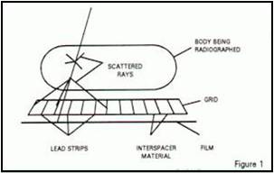
INTERSPACE MATERIAL
THE lead strips are held apart by & parallel by means of a thicker strip of suitable & this separating is the principal function of interspace material.
The grid structure is enveloped in a sealed ALUMINIUM container to protect it from HUMIDITY & MECHANICAL DAMAGE.
The interspace material between grid strips may be
– FIBRE: Transparent to x-ray
– PLASTIC: Transparent to x-ray
– ALUMINUM: Sturdy
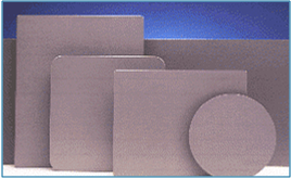
VARIOUS SIZES
Grids are manufactured to accommodate all standard film sizes from 9×12 to 45×45 cm or 8″x10″ to 18″x18“
Customized grids to specifications are available upon request
Grids for use inside cassettes are 3 mm (1/8″) smaller than the corresponding film size, whereas grids for use outside the cassettes are approximately 20 mm (1″) larger than the corresponding film size
Extra large grids are made from two or more smaller sized grids that can be fitted together up to a maximum size of 49 cm x 49 cm (19″x19″)
CONSTRUCTION OF GRIDS
The prime purpose of a grid being the absorption of stray radiation, lead strips (the material which is most practical in the absorption of x-rays) are its basic component.
The strips — five hundred or two thousands or more of them — are set on edge, properly angled to a mean focal distance and separated by x-ray transparent interspacers.
The whole is bonded together into a single flat structure, suitably covered for strength, durability and protection against moisture.
TYPES
STATIONARY GRIDS
1. LINEAR GRIDS WAFER GRIDS
2. FOCUSED GRIDS GRID CASSETTE
3. PSEUDO-FOCUSED GRIDS GRID CAP.
4. CROSSED GRIDS
MOVING GRIDS
1. Single stroke
2. Oscillating and reciprocating
Grid pattern
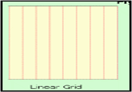
Linear
Crossed.
The linear grid is made with the lengths of all its leads in the same direction.
THE over all size may be quite large since it has to cover the whole film area.
CROSSED GRID
The crossed grid is usually two linear grids, one on top of the other, with the leads of the top grid crossing those of the lower grid
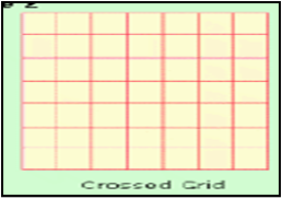
the crossed grid will remove more scattered radiation than a linear grid of ratio equal to the combined ratios of its two parts, e.g., a crossed grid, each of whose parts has 5:1 ratio, will remove more scattered radiation than a linear grid of 10:1 ratio. This advantage is more striking at voltages under 100 KVP.
In these circumstances a high grid ratio is required and often better to use crossed grid of smaller ratio e.g. Two crossed grid of ratio 7 is better than single grid of 15
When using crossed grid, x-ray beam must be perpendicular and no large amount of angulation to any direction
The advantage of the linear grid over the crossed grid is that it may be used in tilted-tube techniques without undue “cut-off” in the radiograph.
This is true with grid ratios 8:1 and lower and only if the angle of tilt of the tube is in a direction parallel to the length of the leads
GRID FOCUS
It refers to the orientation of of lead lines.
Accordingly –
parallel (non focused)
focused.
The focused grid has its leads angled progressively in such a way that lines drawn through each lead and continued out of the grid will intersect at a point known as the grid focus.
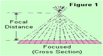
It has the lead strips angulated towards the focal spot
their path coincides with the direction of the paths of diverging photons in the primary x-ray beam, there by accommodating their passage through the grids
there is no reduction in the primary towards the edge.
can be used only within a range of distances from the focal spot where the alignment of lead strips closely coincides the path diverging x-ray beam
The range of distance is specified on the grid
ADVANTAGE
Allows more transmitted photons to reach the receptor.
DISADVANTAGE
Should be used at a distance at which it is designed
The central ray must pass through the grid centre 1 cm error can be included
Correct the face of the grid towards the tube